My previous post describes the hardware challenge Flag Digger and a solution using Bus Pirate and flashrom.
I also own an HydraBus (recommended by @Baldanos). I received it just before Ph0wn but I was not able to use it: when I plugged it into my laptop, nothing happened. I tried with a second USB cable, same result. With another computer, same. During Ph0wn, @Baldanos tested my HydraBus and it worked perfectly. So I tried another USB cable, and Holly Britney! It was the fault of my two USB cables! I made the mistake to use USB cables provided with some Android phones I have. Apparently, not all wires are connected.
So back to home I wanted to discover HydraBus and experiment with it. So why not solving again the Flag Digger with HydraBus?
Note: @Baldanos has also published his own writeup: https://research.kudelskisecurity.com/2018/12/19/ph0wn-2018-flag-digger/
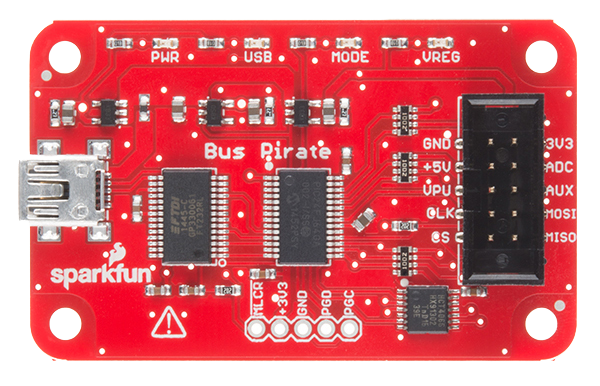
As mentioned in my previous post, Bus Pirate is a very good device for hardware hacking as it supports many protocols, is relatively well documented and is easy to use. But the status of Bus Pirate is also unclear: there are currently two hardware versions: 3.6 (mature) and 4.0 (experimental). Version 4 is experimental for a long time now, and it is unclear if it will become mature one day. Moreover, on the web site of Dangerous Prototypes you can read (under Download):
Unfortunately it seems that Dangerous Prototypes have abandoned the Bus Pirate firmware development (and the Bus Pirate v4 also), despite that their official firmware has never reached a truly stable state: the quantity of bug report threads at forums, especially regarding flashrom, is a direct proof of that.
The official GitHub repository has not been updated between 2015 and 2018. In 2018, there are only a few commits. The last one talks about a v5 hardware!?
There is also a community-driven firmware. The latest version I was able to find is version 7.1 with bootloader 4.5:
HiZ>i
Bus Pirate v3.5
Community Firmware v7.1 - goo.gl/gCzQnW [HiZ 1-WIRE UART I2C SPI 2WIRE 3WIRE KEYB LCD PIC DIO] Bootloader v4.5
DEVID:0x0447 REVID:0x3046 (24FJ64GA00 2 B8)
http://dangerousprototypes.com
One major inconvenient of Bus Pirate version 3 is its limited Flash space (only 64KiB) and SRAM (8KiB). Version 4 is better: 256KiB of Flash and 16KiB of SRAM but it remains low.
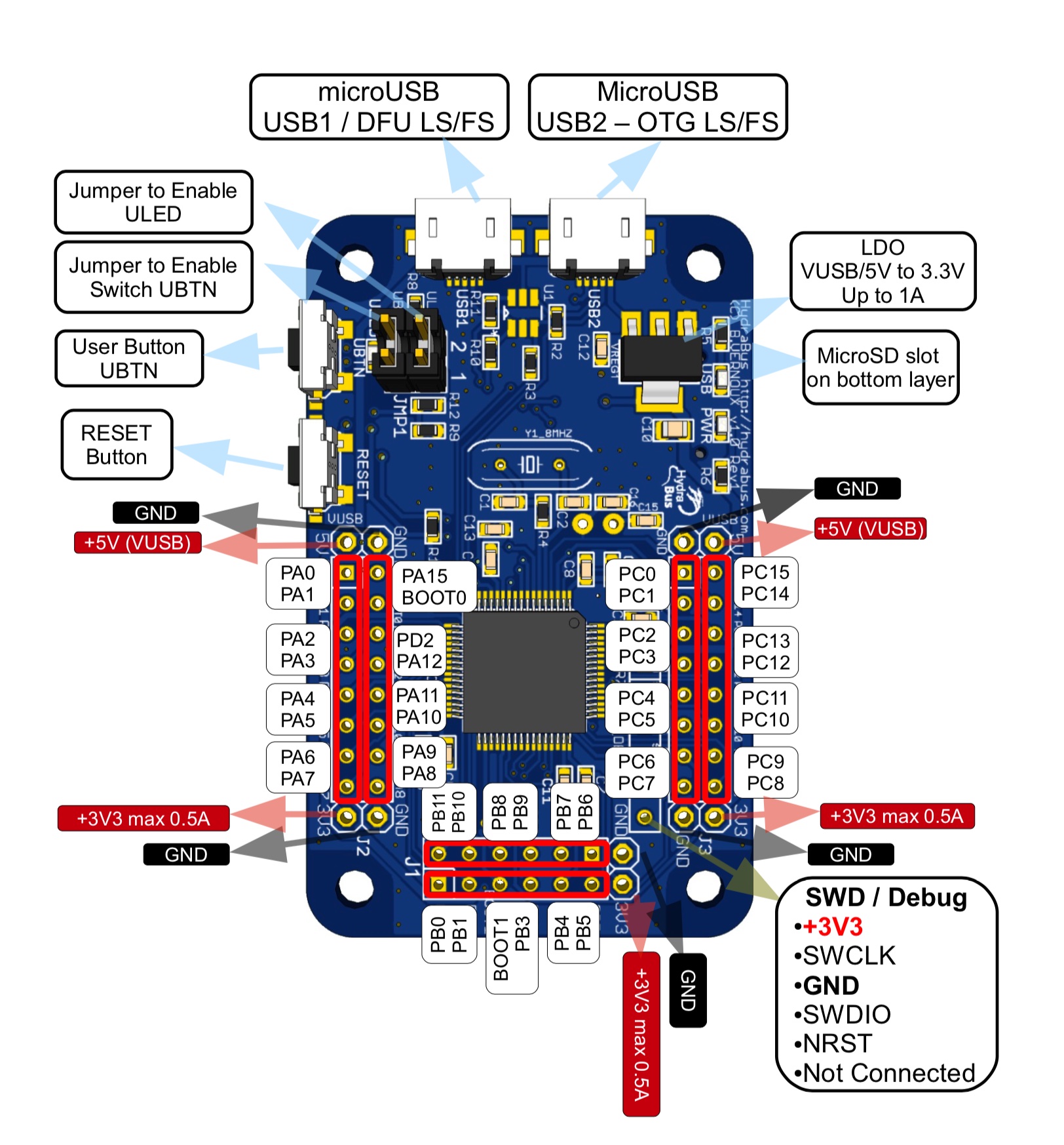
The hardware of HydraBus is impressive: two microUSB ports, a microSD slot, 44 I/O (!), a MCU ARM 32-bit Cortex, 1MiB of Flash memory and 192KiB of SRAM. Far beyond Bus Pirate.
For an unknown reason, my HydraBus was not working as expected (even with the right USB cable). I had problems with the SPI mode (it hangs). After searching, I found that the device was delivered with an old firmware (HydraFW (HydraBus) v0.5-beta-13-g2509b8e 2015-03-28). I flashed the most recent one (HydraFW (HydraBus) v0.9-beta-0-g17a50ac 2018-09-30) and it works perfectly.
To connect to HydraBus, use your favorite terminal emulator. I like to use the (commercial) SecureCRT tool on Windows or macOS. On Windows, people are often using PuTTY. On macOS and Linux, yout can install and use screen, a command line tool. There are plenty of other ways to connect. In the following, I will use screen.
First, we need to determine the port name. One way it to run the command:
ls -l /dev/tty.*
before connecting the HydraBus to the USB port of the computer, and again after. If everything goes well, you have a new entry listed such as /dev/tty.usbmodem14101. Then you can connect with:
screen /dev/tty.usbmodem14101
Note: You do not need to specify the speed.
Then press Enter and HydraBus displays a prompt. Type help to see the available commands:
> help
Available commands
   help           Available commands
   history        Command history
   clear          Clear screen
   show           Show information
   logging        Turn logging on or off
   sd             SD card management
   adc            Read analog values
   dac            Write analog values
   pwm            Write PWM
   frequency      Read frequency
   gpio           Get or set GPIO pins
   spi            SPI mode
   i2c            I2C mode
   1-wire         1-wire mode
   2-wire         2-wire mode
   3-wire         3-wire mode
   uart           UART mode
   nfc            NFC mode
   can            CAN mode
   sump           SUMP mode
   jtag           JTAG mode
   random         Random number
   flash          NAND flash mode
   wiegand        Wiegand mode
   lin            LIN mode
   debug          Debug mode
>
To get some help about a command, type help followed by the name of the command:
> help show
Show information
   system
   memory
   threads
   sd
   debug
> show system
HydraFW (HydraBus) v0.9-beta-0-g17a50ac 2018-09-30
sysTime: 0x00202818.
cyclecounter: 0x3e474864 cycles.
cyclecounter64: 0x000000003e474876 cycles.
10ms delay: 1680021 cycles.

MCU Info
DBGMCU_IDCODE:0x100F6413
CPUID:        0x410FC241
Flash UID:    0x2A0019 0x31374707 0x33373331
Flash Size:   1024KB

Kernel:       ChibiOS 4.0.4
Compiler:     GCC 4.9.3 20150529 (release) [ARM/embedded-4_9-branch revision 227977]
Architecture: ARMv7E-M
Core Variant: Cortex-M4F
Port Info:    Advanced kernel mode
Platform:     STM32F4x5 High Performance with DSP and FPU
Board:        HydraBus 1.0
Build time:   Sep 30 2018 - 14:33:13
To switch to SPI mode, type spi and then Enter:
> spi
Device: SPI1
GPIO resistor: floating
Mode: master
Frequency: 320khz (650khz, 1.31mhz, 2.62mhz, 5.25mhz, 10.50mhz, 21mhz, 42mhz)
Polarity: 0
Phase: 0
Bit order: MSB first
spi1>
Note: The SPI mode is in MSB first by default (Most Significant Byte first).
Type show pins to determine how to wire the HydraBus:
spi1> show pins
CS:   PA15
SCK:  PB3
MISO: PB4
MOSI: PB5
spi1>
The syntax of the commands is similar to the syntax of Bus Pirate (but not identical). Here is a non-exhaustive list:
| Value | Description |
|---|---|
[ |
Chip select (CS) active (low). |
] |
CS disable (high). |
r |
Read one byte by sending dummy byte (0xff). r:1…255 for bulk reads. |
hd |
Read one byte by sending dummy byte (0xff). hd:1…4294967295 for bulk reads. Displays a hexdump of the result. |
w |
Followed by values to write byte(s). w:1…255 for bulk writes. |
0b |
Write this binary value. Format is 0b00000000 for a byte, but partial bytes are also fine: 0b1001. |
0 |
Write this Octal value. Format is prefixed by a 0 (values from 000 to 077) |
0h/0x |
Write this HEX value. Format is 0h01 or 0x01. Partial bytes are fine: 0xA. A-F can be lower-case or capital letters. |
0-255 |
Write this decimal value. Any number not preceded by 0x, 0h, or 0b is interpreted as a decimal value. |
" |
Write an ASCII-encoded string |
[ 0x1 0xff 0 10 0b11 077 ]
0x00:20 writes 20 times the value 0x00.The challenge is the following:
Flag digger
Like many IoT devices, your adventure starts with a small chip. Can you find the flag ?
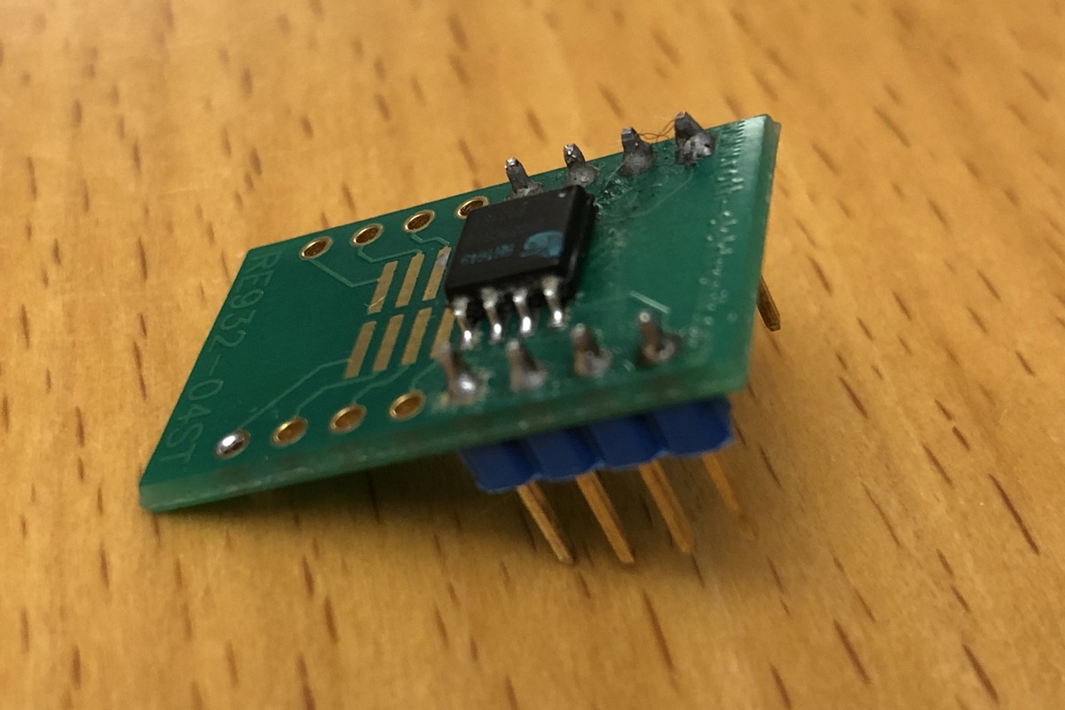
As explained in the previous post, this a Flash memory (25Q32): SPI, 3.3V, 4KiB uniform sector, 32 Mbit, i.e. 4MiB.
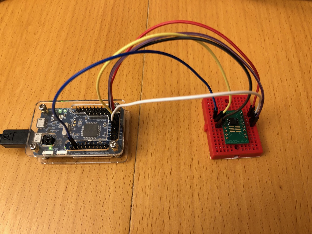
From the information given by show pins, we deduce the wiring:
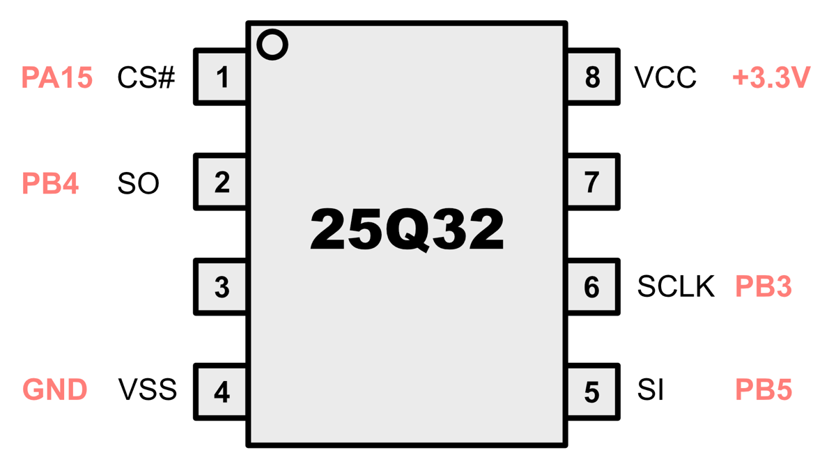
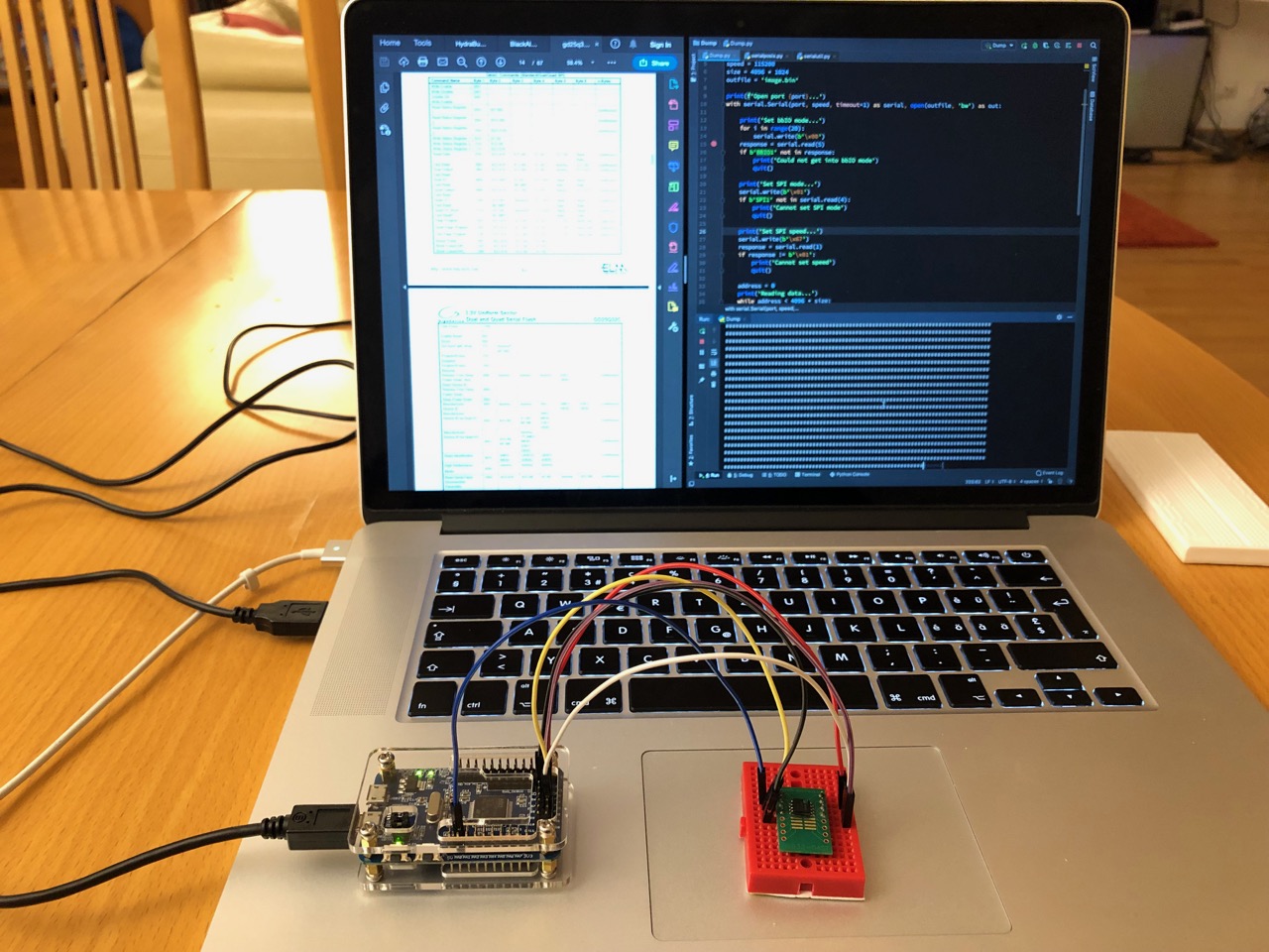
Here is the wired Flash and HydraBus:
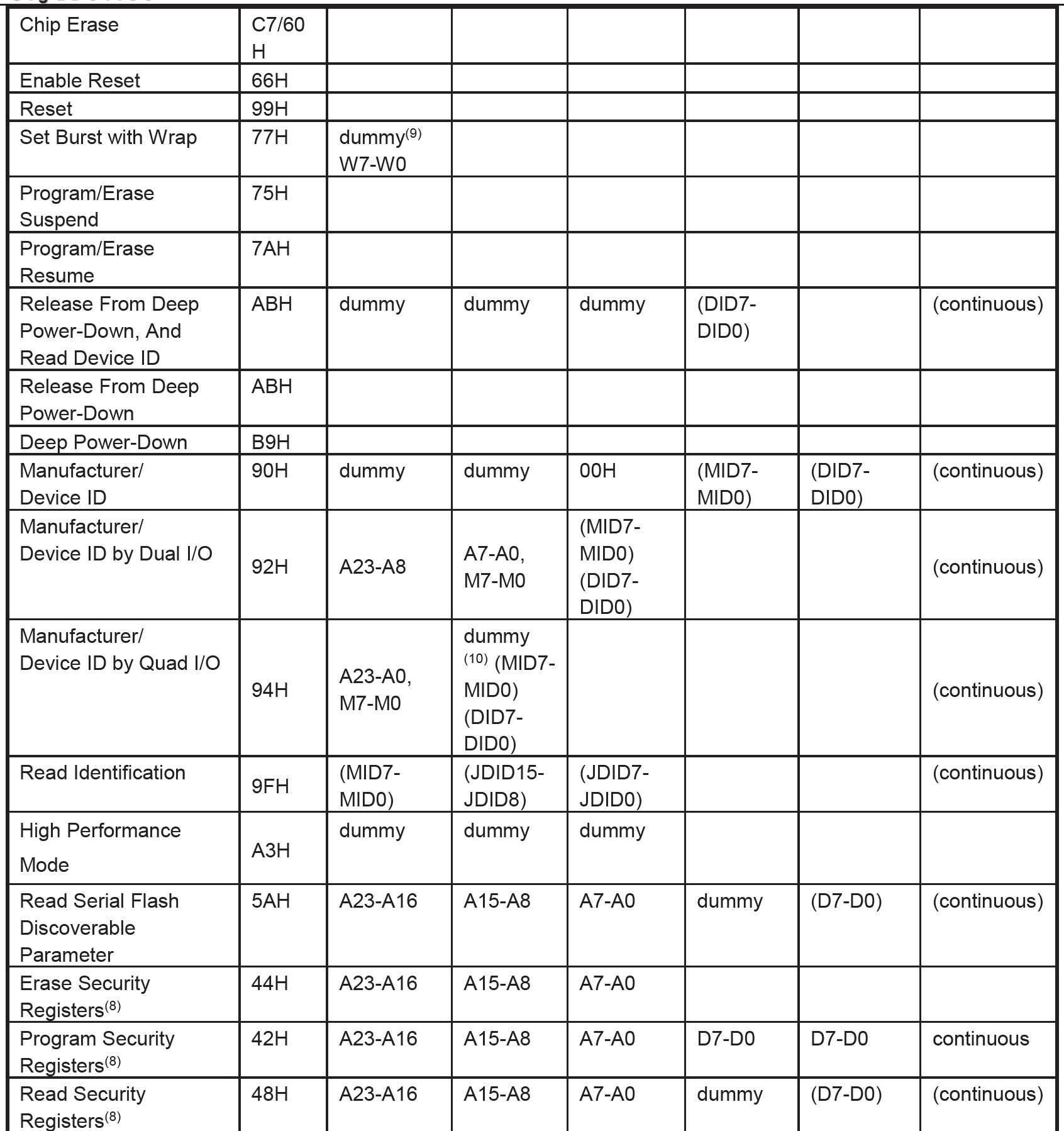
And now what? To go further, we have to study the datasheet of the Flash memory, especially the COMMAND DESCRIPTION paragraph:
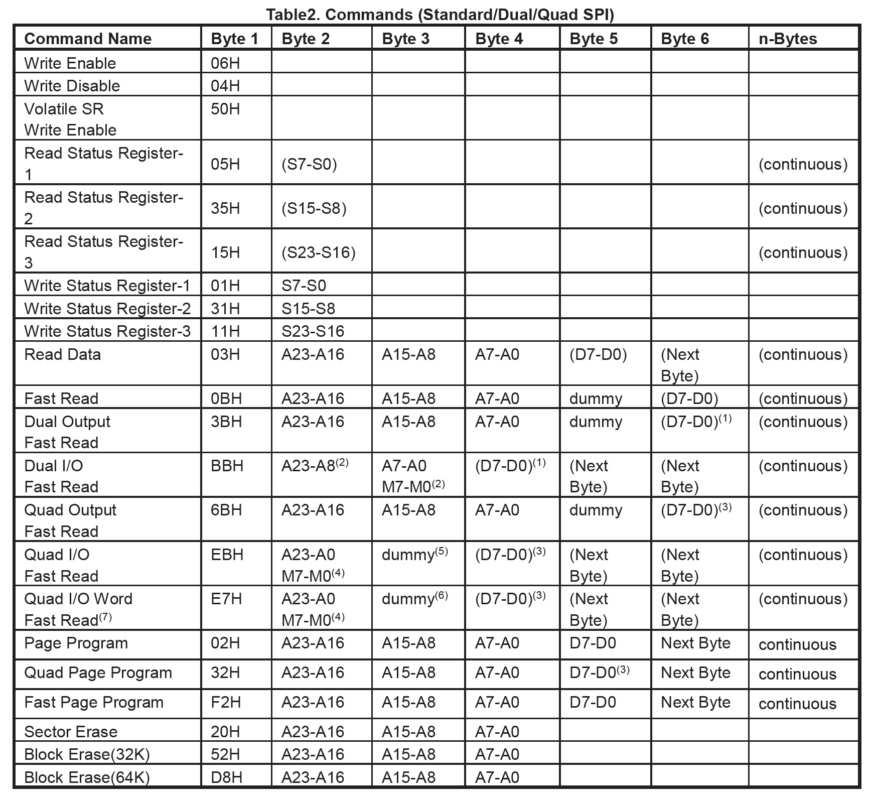
We can, for example, try the command 9F Read Identification to check that everything is working as expected:
spi1> [ 0x9F r:3 ]
/CS ENABLED
WRITE: 0x9F
READ: 0xC8 0x40 0x16
/CS DISABLED
The command can be decomposed this way:
| Value | Description |
|---|---|
[ |
Chip select |
0x9F |
Send the command 9F to the chip. From the datasheet, it means Read Identification |
r:3 |
Read 3 bytes |
] |
Chip unselect |
Note: The spaces are mandatory (contrary to Bus Pirate).
The chip replies with the following bytes: 0xC8 0x40 0x16. This is exactly what is indicated by the datasheet under Table of ID Definitions:
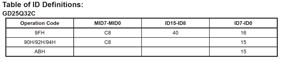
We now know that we are able to send commands to the Flash chip and it replies with the right information.
What we need to do now is to read the content of the flash. Still from the datasheet, we see that we can use the 03 command Read Data followed by the address of the data we want to read (on 3 bytes):
spi1> [ 0x03 0x00:3 hd:32 ]
/CS ENABLED
WRITE: 0x03 0x00 0x00 0x00
68 73 71 73 18 00 00 00  51 8D 12 5C 00 00 02 00  |  hsqs....Q..\....
06 00 00 00 04 00 11 00  C0 00 01 00 04 00 00 00  |  ................
/CS DISABLED
Here we send the command 03, followed by the address 0x000000 (3 bytes), then we read 16 bytes and display them in hexdump format. The result starts with hsqs, the signature of Squashfs, a compressed, read-only file system (see Part 2).
We can dump all the memory this way and then parse the result. But it is not very convenient. Fortunately, HydraBus (like Bus Pirate) has a way to interface with external tools: the binary mode.
The HydraBus Binary mode is a compact protocol which allows scripting:
0x00 (null bytes) to Hydrabus. It should respond with the string BBIO1.0b00000001 (0x01) to Hydrabus. It should respond with the string SPI1.0b01100xxx where xxxrepresents the speed. For example 010 represents 1.31MHz (SPI1). In other terms, we have to send 0b01100010 (0x62).We see previously that to read data, we have to send (i.e. write) the command 03 to the Flash chip. We will thus use the HydraBus Write-then-read operation command (0x04) to do that. Its format is the following:
| Byte 1 | 2, 3 | 4, 5 | 6, ... |
|---|---|---|---|
| command | Bytes to write | Bytes to read | Data to write |
As a reminder, the data we want to send to the Flash chip are the following (for an address of 0x000000):
0x03 0x00 0x00 0x00
So to read 4096 bytes (0x1000, the maximum), we have to sent to HydaBus:
| Byte 1 | 2, 3 | 4, 5 | 6 |
|---|---|---|---|
| HydraBus Command | Bytes to write | Bytes to read | Flash Command |
0x04 |
0x0004 |
0x1000 |
0x03 0x00 0x00 0x00 |
Written byte per byte, it gives (the SPI mode is in MSB first by default):
0x04 0x00 0x04 0x10 0x00 0x03 0x00 0x00 0x00
The read another address, we just need to change the last 3 bytes.
The following Python script does exactly what is explained previously.
Important: This is a Python 3 script. It does not run as-is with Python 2.
import serial
import struct
from datetime import datetime

start_time = datetime.now()

# Adjust these values
port = '/dev/cu.usbmodem14101'  # Name of the USB port to communicate with HydraBus
speed = 115200  # Speed of the communication with HydraBus
size = 1024 * 4096  # Size of the Flash: 4 MiB
outfile = 'image.bin'  # Name of the file to write with the content of the Flash

print(f'Open port {port} at {speed} bps...')
print(f'Open output file {outfile}')
# Open the serial and the file to write
with serial.Serial(port, speed, timeout=1) as serial, open(outfile, 'bw') as out:

    print('Set bbIO mode...')
    for i in range(20):
        serial.write(b'\x00')
    if b'BBIO1' not in serial.read(5):
        print('Could not get into bbIO mode')
        quit()

    print('Set SPI mode...')
    serial.write(b'\x01')
    if b'SPI1' not in serial.read(4):
        print('Cannot set SPI mode')
        quit()

    print('Set SPI speed...')
    serial.write(b'\x62')  # 1.31MHz
    if serial.read(1) != b'\x01':
        print('Cannot set speed')
        quit()

    address = 0  # Start at address 0x000000
    print(f'Reading {size} bytes...')
    while address < size:
        serial.write(b'\x04\x00\x04\x10\x00')  # Write-then-read: write 4 bytes, read 4096 bytes
        serial.write(b'\x03' + struct.pack('>L', address)[1:])  # Read data (addr on 3 bytes, not 4)
        if serial.read(1) != b'\x01':
            print('Error reading data, abort')
            quit()
        buffer = serial.read(4096)  # Read the data from the Flash
        address += 4096  # Increment the address by 4096, the number of bytes read
        out.write(buffer)  # Write the data into the out file
        print('#', end='', flush=True)  # Print some progress
        if (address / 4096) % 80 == 0:  # After 80 columns, go to the next line
            print()

    print()
    print('Go back to bbIO mode...')
    serial.write(b'\x00')
    if b'BBIO1' not in serial.read(5):
        print('Could not go back into bbIO mode')

    print('Go back to Console mode...')
    serial.write(b'\x0F\n')
    if b'Hydrabus' not in serial.read(8):
        print('Could not go back into Console mode')

elapsed_time = datetime.now() - start_time
print(f'Flash dumped: {size} bytes into file {outfile} in {elapsed_time.seconds} seconds')
Before running this script, it may be necessary to reset HydraBus by pressing the Reset button (second button from the top).
$ python Dump.py
Open port /dev/cu.usbmodem14101 at 115200 bps...
Open output file image.bin
Set bbIO mode...
Set SPI mode...
Set SPI speed...
Reading 4194304 bytes...
################################################################################
################################################################################
################################################################################
################################################################################
################################################################################
################################################################################
################################################################################
################################################################################
################################################################################
################################################################################
################################################################################
################################################################################
################################################################
Go back to bbIO mode...
Go back to Console mode...
Flash dumped: 4194304 bytes into file image.bin in 60 seconds
As explained in Part 2, it is now possible to extract the content of the Flash and get the flag from flag.pdf:
$ file flash.bin
flash.bin: Squashfs filesystem, little endian, version 4.0, 655738 bytes, 24 inodes, blocksize: 131072 bytes, created: Thu Dec 13 16:48:17 2018
$ unsquashfs flash.bin
$ open squashfs-root/flag.pdf