Freely translated from Chinese documents © 2015 DWIN Technology.
This document © 2018-2021 Sebastien Andrivet.
DGUS (DWIN Graphic Utilized Software) is a cost effective GUI platform developed by DWIN Technology. MINI DGUS LCM (Liquid Crystal Monitor) is a low-cost and smaller module with DGUS firmware pre-installed, with the same development method as the other DGUS LCM.
The differences between MINI DGUS and DGUS are listed below:
In this version some functions have been excluded, among them the CRC Checksum, firmware update using SD card, user-defined baud rate, Firmware Parameter Config setting, Timer Variable and DWIN OS.
There is also a DGUS II which is another generation of the DGUS (not the DGUS MINI). Examples of such MINI DGUS panels are:
This document is freely translated from the Chinese document MINI DGUS 屏用户开发指南 (Version 2.3 2015.08) with some information taken from other documents such as the English DWIN DGUS Display Development Guide Version 4.3 and some of my own researches.
As I found the original order of chapters confusing, this document uses a different order. Pictures are my own.
Note: I am not affiliated directly or indirectly to DWIN Technology nor endorsed by them. This is my own work for my own purpose (I am developing a firmware for a 3D printer using a MINI DGUS Display). USE IT AT YOU OWN RISK.
There are several versions of the SDK available. Some are for the latest version of the hardware (i.e. DGUS II), some for DGUS and DGUS MINI. Some are translated in English, some only partially. For DGUS MINI, I found that the following SDK works relatively well:
More recent versions (like 7.x or 8.x) may work but are, in general, only partially translated in English.
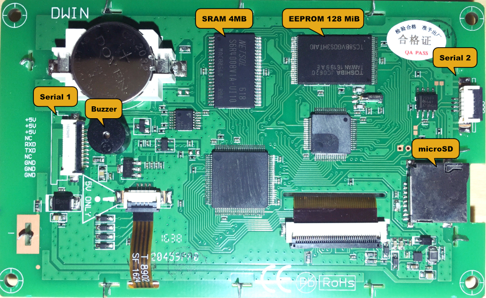
The MINI DGUS Display can be flashed by using its microSD slot (on the right):
IMPORTANT: You have to use a microSD card with a maximum capacity of 8GiB. If you use a microSD card with a greater capacity, the results are unreliable (sometimes it flashes, sometimes not). This is a limitation of the MINI DGUS Display.
The microSD card has to be formatted with the following parameters: FAT32 4096 bytes per cluster (i.e. 8 sectors)
To format it under Linux (and macOS with the dosfstools Homebrew package):
mkfs.fat -F 32 -n SD -s 8 -v /dev/diskN
Of course, replace /dev/diskN with the appropriate value.
To format under Windows (Command Prompt):
format G: /FS:FAT32 /V:LCD /A:4096
Of course, replace G: with the appropriate volume letter.
All files are placed in a DWIN_SET folder, itself in the root of the SD card. These files are typically:
| Name | Description |
|---|---|
CONFIG.TXT |
System settings |
*.BMP |
Images of the pages, 24-bit, 480 x 272 pixels |
*.HZK |
Font, generated with the No.0 Font Lab tool |
*.ICO |
Icons, generated with the DWIN Icon Generator tool |
13*.BIN |
Touch configuration |
14*.BIN |
Variables configuration |
22*.BIN |
Variables initialization |
Some system settings can be configured by creating a CONFIG.TXT file inside the DWIN_SET folder. This is a simple text file with the following format:
R?=HH ; a comment
R? is the identifier of the register (such as R0)HH is the value in hexadecimal (in capital); is optional and everything after it is ignoredFor example
R1=07      ; baudrate:115200
R2=0D      ; FBZ|L22_Init_En|TPSAUTO
R3=5A      ; UART_SYNC_H
RA=A5      ; UART_SYNC_L
Important: The default values for UART_SYNC_H and UART_SYNC_Lare 5A and A5.
| Register | Ranges | Description |
|---|---|---|
| R0 | Depends on the MINI DGUS screen | MINI DGUS screen drive mode selection. Configuration error will lead to abnormal display. Users are not supposed to configure this parameters. |
| R1 | 0x00-0x10 | Serial port 1 baud rate setting. Default baud rate is 115200. |
| R2 | 0x00-0xFF | SYS_CFG |
| R3 | 0x00-0xFF | UART_SYNC_H: Serial header high byte |
| R6 | 0x00-0x40 | Brightness of backlight. 0x40: 100% |
| R7 | 0x00-0x40 | Brightness of backlight in sleep mode. 0x40: 100% |
| R8 | 0x01-0xFF | Light-up time in seconds |
| RA | 0x00-0xFF | UART_SYNC_L: Serial header low byte |
| RB | 0x5A | UNDOCUMENTED by DWIN: reformat the LCD |
The configuration file parameters are one-byte HEX values (must be capitalized), such as 0A for decimal 10. The parameters of the configuration file must have 2 digits, for example 00 cannot be written as 0.
IMPORTANT: Users are not supposed to configure this parameter.
MINI DGUS Display drive mode selection. Configuration error will lead to abnormal display (distorted images).
For information, the modes are defined as:
| R0 | Resolution (HxV) |
|---|---|
| 00 | 640x480 |
| 01 | 640x480 |
| 02 | 800x480 |
| 03 | 800x600 |
| 04 | 1024x768 |
| 05 | 1024x768 |
| 06 | 800x600 |
| 07 | 800x600 |
| 08 | 800x600 |
| 09 | 1024x768 |
| 0A | 1280x800 |
| 0B | 1024x600 |
| 0C | 1366x768 |
| 0D | 480x640 |
| 0E | 320x240 |
| 0F | 480x272 |
| 10 | 480x272 |
| 11 | 800x480 |
| 12 | 320x240 |
Serial port 1 baud rate setting. Default baud rate is 115200.
| R1 | 0x00 | 0x01 | 0x02 | 0x03 | 0x04 | 0x05 | 0x06 | 0x07 |
|---|---|---|---|---|---|---|---|---|
| Baudrate | 1200 | 2400 | 4800 | 9600 | 19200 | 38400 | 57600 | 115200 |
| R1 | 0x08 | 0x09 | 0x0A | 0x0B | 0x0C | 0x0D | 0x0E | 0x0F | 0x10 |
|---|---|---|---|---|---|---|---|---|---|
| Baudrate | 28800 | 76800 | 62500 | 125000 | 250000 | 230400 | 345600 | 691200 | 921600 |
| Bit | Value | Definition | Description |
|---|---|---|---|
| 7 | 0x80 | VDS | 0=Normal display, 1=90° Rotation |
| 6 | 0x40 | HDS | 0=Normal display, 1=180° Rotation (upside-down) |
| 5 | 0x20 | TP_LED | 0=backlight is not controlled by touch screen state, 1=backlight is controlled by touch screen state R6, R7, R8 |
| 4 | 0x10 | FCRC | 0=Disable CRC16 checksum for serial communication, 1=Enable CRC16 checksum for serial communication |
| 3 | 0x08 | TPSAUTO | 0=Disable auto-upload of key code, 1=Enable auto-upload of key code |
| 2 | 0x04 | L22_Init_En | 0=Initialize variables (56KB) with 0x00, 1=Initialize variables with data from 22*.bin |
| 1 | 0x02 | Reserved | |
| 0 | 0x01 | FBZ | 0=Enable buzzer when clicking valid area, 1=Disable buzzer. It can still be controlled by the BZ_TIME (0x02) Register. |
Frame header. R3 is the first byte of the frame header (high order byte). RA is the second byte of the frame header (low order byte).
IMPORTANT: Users are not supposed to configure this parameter.
Due to TCON difference on display, there are two kinds of initial displaying data and R4 is used to setting the timing relation of the input data and clock:
R1 is between 0x00 and 0x10, R5 and R9 are unused.R1 is equal to 0x11, R5 and R9 define the baud rate:baudrate = 6250000 / R5:R9
For example, if R5=0x02 and R9=0x71, the corresponding baud rate is 10000bps:
R5:R9 = 0x0271 = 625
baudrate = 6250000 / 625 = 10000bps
These three registers control the back light if TP_LED (register R2 bit 5) is set to 1.
| Register | Range | Description |
|---|---|---|
| R6 | 0x00-0x40 | Normal brightness of the screen |
| R7 | 0x00-0x40 | Brightness in standby mode |
| R8 | 0x00-0xFF | Time after which the standby mode is activated |
Example:
R2.5=1, R6=40, R7=10, R8=1E: If there is no touch within 30 seconds (0x1E = 30), brightness will go down to 25% (0x10). It will go back to 100% (0x40) if the user press the screen.
See R5.
See R3.
IMPORTANT: This is not documented in the original Chinese document. If you create a CONFIG.TXT file in the DWIN_SET directory with content:
RB=5A
it reformats the LCD display: all the images are erased and the default settings of the LCD are loaded. During the process, the screen becomes blue. When the process is finished, it becomes white-gray.
Insert the microSD card inside the slot of the MINI DGUS Display (on the right side in this picture):
The display turns blue and the flashing process begins. After a few seconds, every image is displayed one by one. When the sequence of images stops, you can remove the microSD card and power-off / power-on the display.
Tap very quickly on an area of the display that is not a button. You have to tap 20 times in less than 4 seconds. When entering calibration mode, the display emits a long beep and turns blue.
Follow the instructions on the screen (such as Press The Cross Dot In Left_Top.) and when it is finished, the display returns to the starting page.
Add a line with TP_CORRECT in the CONFIG.TXT file inside the DWIN_SET folder. Then place the microSD card in the slot (like for flashing). When entering calibration mode, the display emits a long beep and turns blue.
Follow the instructions on the screen (such as Press The Cross Dot In Left_Top.)
When the calibration is done, remove the microSD card and then remove the TP_CORRECT line in the CONFIG.TXT file.
Note: Some documents (from DWIN) indicate to create a CONFIG.TXT in the root of the microSD card. From my own tests, this is wrong. The file has to be in the DWIN_SET folder.
To disable the SD card, write SD_LOCK_1000_12345678 in CONFIG.TXT and plug the microSD card into the DGUS module. In this example, 1000 is the address of the password in SRAM (0x0000-0x3FFF), 12345678 is the password to reenable the SD slot (8 bytes).
A5 5A 0B 82 10 00 31 32 33 34 35 36 37 38 (command 0x82 - Write SRAM - at address 0x1000).SD_UNLOCK_12345678 in CONFIG.TXTWARNING: Failure to input correctly the password will definitively lock the SD slot.
The MINI DGUS Display uses these formats to represent data:
| Data Type | Min (dec) | Min (hex) | Max (dec) | Max (hex) |
|---|---|---|---|---|
| Integer | -32768 |
0x8000 |
+32767 |
0x7FFF |
| Long Integer | -2147483648 |
0x80000000 |
+2147483647 |
0x7FFFFFFF |
| Character | 0 |
0x00 |
255 |
0xFF |
The MINI DGUS Display uses different spaces for permanent or temporary storage of data:
| Space | Memory | Addresses | Description |
|---|---|---|---|
| Registers | RAM | 0x00-0xFF |
256 registers (256 B) |
| Variables | RAM | 0x0000-0x0FFF |
4 KW (05 series) |
| Curves buffer | RAM | 0-3 or 0-1 |
4 or 2 curves |
| Fonts | FLASH | 0-127 |
128 blocks of 128 KW |
| Pictures | FLASH | 0-349 |
96 MB, ~350 pictures |
Note: 02 series have only 4 KW of RAM for Variables (0x0000 to 0x07FF).
The 32 MB of flash memory for Libraries are divided into 128 blocks of 128 KW (256 KB):
| Font ID | Size KB | Description |
|---|---|---|
| 0 | 3072 | #0 ASCII font |
| 12 | 256 | System use |
| 13 | 256 | Touch configuration |
| 14 | 2048 | Variables configuration |
| 22 | 256 | Variable initialization |
| 23 | 256 | OS program |
| 24-127 | 26K | User defined |
The MINI DGUS Display uses 96 MB of Flash memory to store 350 pictures. The images have the following format:
The last point is very important. The LCD (i.e. DGUS) is not able to handle other formats like top-down bitmaps. To convert images to the right format, you can use the Image Converter provided with the DGUS SDK or image editors such as Photoshop. You can also use ImageMagick:
convert 180.bmp -resize 480x272 BMP3:180.bmp
To convert all images:
for f in *.bmp; do convert "$f" -resize 480x272 BMP3:"$f"; done
The MINI DGUS Display provides 256 registers used to control the behavior of the system:
| Address | Name | Size | Description |
|---|---|---|---|
| 0x00 | Version | 1 | MINI DGUS Display version number in BCD, 0x10 indicates 1.0 |
| 0x01 | LED_NOW | 1 | LED brightness 0x00-0x40 |
| 0x02 | BZ_TIME | 1 | Buzzer beeping time, x 10ms |
| 0x03 | PIC_ID | 2 | Read: Current picture ID, Write: Jump to picture |
| 0x05 | TP_Flag | 1 | 0x5A: Screen was touched. Write 0x00 to clear after reading |
| 0x06 | TP_Status | 1 | 0x01: first click. 0x03: pressing down. 0x02: uplift pressing, others: invalid |
| 0x07 | TP_Position | 4 | Coordinate of touching position: X H:L, Y H:L |
| 0x0B | TPC_Enable | 1 | 0x00: disable touch panel, others: Enable touch panel, default: 0xFF |
| 0x0C-0x0F | 4 | Reserved | |
| 0x10-0x1A | R0-RA | 11 | Mapping of SD card config registers (read only except for R2 which is read/write) |
| 0x1B-0x1E | 4 | Reserved | |
| 0x1F | RTC_COM_ADJ | 1 | 0x5A: RTC data is rewritten through serial port, clear after RTC auto updating |
| 0x20 | RTC_NOW | 16 | Current date and time: YY:MM:DD:WW:HH:MM:SS |
| 0x30-0x3F | 16 | Reserved | |
| 0x40 | En_Lib_OP | 1 | 0x5A: applying writing in font flash memory, clear after operation |
| 0x41 | Lib_OP_Mode | 1 | 0xA0: Reads data of the specified font space into the variable memory space, 0x50: Write all variable space data to the corresponding font |
| 0x42 | Lib_ID | 1 | Font address for data exchange (0x40-0x7F), 128 KW per font, maximum flash space is 8MW (16MB) |
| 0x43 | Lib_Address | 3 | Address in font library for data exchange, specify the first (word) address for data operation in font storage,0x00:00:00-0x01:FF:FF |
| 0x46 | VP | 2 | Variable SRAM addresses for data exchange, 0x00:00-0x3F:FF (05 series) |
| 0x48 | OP_Length | 2 | Length of exchanged data, by word. 0x00:01-0x3F:FF (05 series) |
| 0x4A | Timer0 | 2 | 16-bit software timer, in term of 4ms, auto-decrement to 0 |
| 0x4C | Timer1 | 1 | 8-bit software timer, in term of 4ms, auto-decrement to 0 |
| 0x4D | Timer2 | 1 | 8-bit software timer, in term of 4ms, auto-decrement to 0 |
| 0x4E | Timer3 | 1 | 8-bit software timer, in term of 4ms, auto-decrement to 0 |
| 0x4F | Key_Code | 1 | User key code, used to trigger 13*.BIN touch configuration file, 0x00: invalid, cleared after processing |
| 0x50-0xEA | 155 | Reserved | |
| 0xEB | CURVE_CLR | 1 | 0x5A-0x5B:Clear channel CH0-CH1, register return to 0 after clear up |
| 0xEC | FAST_REF | 1 | 0x5A: Enter fast refresh mode (no refresh of the back), 0x00 to exit fast refresh mode |
| 0xED-0xFF | Reserved |
Notes:: Sizes are in words (2 bytes). * All values are in Big Endian
The MINI DGUS Display provides 8 KW/16kB (05 series) or 4 KW/8kB (02 series) of RAM for storing GUI variable data. The address range is 0x0000-0x3FFF. Each address represents a word (2 bytes, in big endian order).
Variable memory space is accessed using 0x82/0x83 commands.
In order to simplify the display of the real-time curves, the MINI DGUS Displays have a curve data buffer for buffering the user's curve data. This buffer does not occupy the data memory space and can buffer up to 4 curves at the same time (2 for 02 series).
Curve data buffer is accessed using 0x84 commands (write only).
Curve data buffer can only be written in words, and the data for each curve point is represented by a 2-byte signed integer. It is possible to clear the first and second curves by writing 0x5A or 0x5B to the 0xEB register.
The MINI DGUS Displays are equipped with two (05 series) or one (02 series) asynchronous, full-duplex serial ports (UART). Each byte occupies 10 bits: 1 start bit, 8 data bits, 1 stop bit and no parity (8N1).
The serial port 1 baud rate is configured by the SD card, and the serial port 2 (if present) is fixed to 115200 bps.
The serial port 1 and serial port 2 use the same frame structure. All data are transferred in MSB order, i.e. to transfer 0x1234, 0x12 is transferred first then 0x34.
| Serial port | Port 1 | Port 2 |
|---|---|---|
| 0x80~0x84 commands | Supported in non-modbus config | Supported |
| Modbus host | Supported in modbus config | No support |
| Frame header configuration | Supported | Supported |
| Baud rate configuration | Supported | 115200 bps |
| Perss touchscreen active return | Supported | No support |
| 485 level expansion | Supported | No support |
| OS online debugging function | No support | Supported |
Data frames consist of up to 4 blocks as described in this table:
| Block | Name | Size | Comment |
|---|---|---|---|
| 1 | Header | 2 | Defined by R3 & RA |
| 2 | Data length | 1 | Data length, including Command and Data (n+1) |
| 3 | Command | 1 | 0x80-0x84 |
| 4 | Data | n | Payload of the frame |
Notes:
The default values for R3 (UART_SYNC_H) and RA (UART_SYNC_L) are 5A and A5. So the frames begin with the bytes 5A A5.
* All values are in Big Endian.
The maximum data length that can be transmitted is 248 bytes.
It is not clear if MINI DGUS Displays are able to support CRC like DGUS displays. Some parts of the documentation suggest it is the case, but the data sheets suggest the contrary. I have assumed that MINI DGUS displays do not support CRC.
| Command | Value | Data | Description |
|---|---|---|---|
| Write Register | 0x80 | REG + DATA | Write data into registers |
| Read Register | 0x81 | REG + LEN | Read data from registers |
| Response | Value | Data | Description |
|---|---|---|---|
| Read Register | 0x81 | REG + LEN + DATA | Response from the MINI DGUS Display |
REG is between 0x00 and 0xFF and designates the first register to read of write. LEN is between 0x00 and 0xFF and designates the length (in bytes) of the data to read or write. DATA is the sequence of bytes to write or returned by the MINI DGUS Display.
| Command | Value | Data | Description |
|---|---|---|---|
| Write SRAM | 0x82 | ADDR + DATA | Write data into SRAM memory |
| Read SRAM | 0x83 | ADDR + LEN | Read data from SRAM memory |
| Response | Value | Data | Description |
|---|---|---|---|
| Read SRAM | 0x83 | ADDR + LEN + DATA | Response from the MINI DGUS Display |
ADDR is between 0x0000 and 0x3FFF and designates the address of the first word to read of write. LEN is between 0x00 and 0x7F and designates the length (in words) of the data to read or write. DATA is the sequence of words to write or returned by the MINI DGUS Display.
| Command | Value | Data | Description |
|---|---|---|---|
| Write curves | 0X84 | CH_MODE + DATA | Write data into the curves buffer |
CH_MODE defines the channels order. Each bit of CH_MODE corresponds to a channel: Bit 0 corresponds to channel 0, and bit 1 corresponds to channel 1, ... Each bit set (1) in CH_MODE indicates that DATA contains data for the corresponding channel. For example if CH_MODE is equal to 0x0B, DATA has the following format: (channel0|channel1|channel3) | ... | (channel0|channel1|channel3). Each channel data is a 16-bit unsigned integer.
13*.BIN)The Touch Configuration File (13*.BIN) contains touch (input) commands and can be generated with the DGUS SDK. Each command occupies 16, 32 or 48 bytes and include 6 parts:
| Part | Name | Size | Description |
|---|---|---|---|
| 1 | Pic_ID | 2 | Picture/Page ID |
| 2 | TP_Area | 8 | Touch button area: (Xs,Ys) (Xe,Ye). When Xs=0xFFFF, the button is triggered by the key code in register 0x4F, Ys_H is the setting |
| 3 | Pic_Next | 2 | Jump to this Picture ID, 0xFF??: no jump |
| 4 | Pic_On | 2 | Picture ID for the press-down effect, 0xFF??: no effect |
| 5 | TP_Code | 2 | Touch key code. 0xFF??: invalid key code, 0xFE??: Function button (0xFE00: Variable Data Input), 0x00??: key code in ASCII (0x0031: 1) |
| 6 | TP_FUN | 32 | When TP_Code is 0xFE??, parameters of the button |
| TP_Code | Command | Description |
|---|---|---|
| 0xFE00 | Variable Data Input | Input integer or fixed-point decimal number |
| 0xFE01 | Popup Menu | Displays a popup menu |
| 0xFE02 | Incremental Adjustment | Incremental adjustment of a value (both increment or decrement) with adjustable steps and boundaries |
| 0xFE03 | Slider Adjustment | Adjustment of a slider |
| 0xFE04 | RTC Settings | Touch keyboard to set RTC (Real Time clock) |
| 0xFE05 | Return Key Code | Send a value into a variable when a button is pressed |
| 0xFE06 | Text Input | Input text |
| Offset | Name | Size | Description |
|---|---|---|---|
| 0x00 | Pic_ID | 2 | Picture/Page ID |
| 0x02 | TP_Area | 8 | Touch button area (Xs, Ys) (Xe, Ye) |
| 0x0A | Pic_Next | 2 | Jump to this Picture ID, 0xFF: none |
| 0x0C | Pic_On | 2 | Press-down effect, 0xFF: none |
| 0x0E | TP_Code | 2 | 0xFE00 |
| 0x10 | 1 | 0xFE |
|
| 0x11 | VP | 2 | Variable address |
| 0x13 | V_Type | 1 | Variable format: 0x00: integer (word), 0x01: long integer (dword), 0x02: unsigned byte (high byte at VP address), 0x03: unsigned byte (low byte at VP address, 004: double long integer (qword) |
| 0x14 | N_Int | 1 | Integer digits |
| 0x15 | N_Dot | 1 | Decimal digits |
| 0x16 | (x,y) | 4 | Position of cursor, right aligned |
| 0x1A | Color | 2 | Font color |
| 0x1C | Lib_ID | 1 | ASCII Font ID, 0x00: default #0 ASCII font |
| 0x1D | Font_Hor | 1 | Font size horizontally |
| 0x1E | Cursor_Color | 1 | Color of cursor, 0x00: black, others: white |
| 0x1F | Hide_En | 1 | 0x00: hidden display (replaced by *), others: unhidden |
| 0x20 | 1 | 0xFE | |
| 0x21 | KB_Source | 1 | 0x00: keyboard on current page, other: from KB_Source page |
| 0x22 | PIC_KB | 2 | Picture ID of keyboard, 0x00 if KB_Source = 0x00 |
| 0x24 | Area_KB | 8 | Keyboard ares (Xs, Ys, Xe, Ye). 0x00 if KB_Source = 0x00 |
| 0x2C | Area_KB_Position | 4 | Keyboard display position, 0x00 if KB_Source = 0x00 |
| 0x30 | 1 | 0xFE | |
| 0x31 | Limits_En | 1 | 0xFF: enable range limit |
| 0x32 | V_Min | 4 | Minimal value |
| 0x36 | V_Max | 4 | Maximum value |
| 0x3A | 6 | 0x00 |
| Key codes | Description |
|---|---|
0x0030 –0x0039 |
Number 0-9 |
0x002E |
. |
0x002D |
+ / - |
0x00F0 |
Cancel |
0x00F1 |
Confirm |
| Offset | Name | Size | Description |
|---|---|---|---|
| 0x00 | Pic_ID | 2 | Picture/Page ID |
| 0x02 | TP_Area | 8 | Touch button area (Xs, Ys) (Xe, Ye) |
| 0x0A | Pic_Next | 2 | Jump to this Picture ID, 0xFF: none |
| 0x0C | Pic_On | 2 | Press-down effect, 0xFF: none |
| 0x0E | TP_Code | 2 | 0xFE01 |
| 0x10 | 1 | 0xFE |
|
| 0x11 | VP | 2 | Variable address |
| 0x13 | VP_Mode | 1 | 0x00: write key code in VP, 0x01: write key code in VP high byte, 0x02: write key code in VP low byte, 0x10-0x1F: write key code lowest bit to VP specified bit (0x10=bit 0) |
| 0x14 | Pic_Menu | 2 | Picture ID of the menu |
| 0x16 | AREA_Menu | 8 | Coordinates of the menu (Xs, Ys) (Xe, Ye) |
| 0x1E | Menu_Position_X | 2 | Position (X) of the menu on the current page |
| 0x20 | 1 | 0xFE |
|
| 0x21 | Menu_Position_Y | 2 | Position (Y) of the menu on the current page |
| 0x23 | 13 | 0x00 |
| Offset | Name | Size | Description |
|---|---|---|---|
| 0x00 | Pic_ID | 2 | Picture/Page ID |
| 0x02 | TP_Area | 8 | Touch button area (Xs, Ys) (Xe, Ye) |
| 0x0A | Pic_Next | 2 | 0xFF |
| 0x0C | Pic_On | 2 | Press-down effect, 0xFF: none |
| 0x0E | TP_Code | 2 | 0xFE02 |
| 0x10 | 1 | 0xFE |
|
| 0x11 | VP | 2 | Variable address |
| 0x13 | VP_Mode | 1 | 0x00: adjust value in VP (integer), 0x01: adjust value in VP high byte, 0x02: adjust value in VP low byte, 0x10-0x1F: adjust lowest bit of specified bit in VP (0x10=bit 0) |
| 0x14 | Adj_Mode | 1 | 0x00: decrement, others: increment |
| 0x15 | Return_Mode | 1 | 0x00: does not cycle, other: cycle |
| 0x16 | Adj_Step | 2 | Step size: 0x0000-0x7FFF |
| 0x18 | V_Min | 2 | Minimal value |
| 0x1A | V_Max | 2 | Maximal value |
| 0x1C | 3 | 0x00 |
| Offset | Name | Size | Description |
|---|---|---|---|
| 0x00 | Pic_ID | 2 | Picture/Page ID |
| 0x02 | TP_Area | 8 | Touch button area (Xs, Ys) (Xe, Ye) |
| 0x0A | Pic_Next | 2 | 0xFF |
| 0x0C | Pic_On | 2 | 0xFF |
| 0x0E | TP_Code | 2 | 0xFE03 |
| 0x10 | 1 | 0xFE |
|
| 0x11 | VP | 2 | Variable address |
| 0x13 | Adj_Mode | 1 | 0x0?: adjust value in VP (integer), 0x1?: adjust value in VP high byte, 0x2?: adjust value in VP low byte, 0x?0: Horizontal, 0x?1: Vertical |
| 0x14 | Area_Adj | 8 | Effective sliding area (=TP_Area) |
| 0x1C | V_begin | 2 | Value corresponding to start position |
| 0x1E | V_end | 2 | Value corresponding to end position |
Note: To prevent maloperation, you must press the effective drag area for more than 0.5 seconds before sliding starts
| Offset | Name | Size | Description |
|---|---|---|---|
| 0x00 | Pic_ID | 2 | Picture/Page ID |
| 0x02 | TP_Area | 8 | Touch button area (Xs, Ys) (Xe, Ye) |
| 0x0A | Pic_Next | 2 | Jump to this Picture ID, 0xFF: none |
| 0x0C | Pic_On | 2 | Press-down effect, 0xFF: none |
| 0x0E | TP_Code | 2 | 0xFE04 |
| 0x10 | 1 | 0xFE |
|
| 0x11 | VP | 3 | 0x00 |
| 0x14 | (x,y) | 4 | Position of cursor, right aligned |
| 0x18 | Color | 2 | Font color |
| 0x1A | Lib_ID | 1 | ASCII Font ID, 0x00: default #0 ASCII font |
| 0x1B | Font_Hor | 1 | Font size horizontally |
| 0x1C | Cursor_Color | 1 | Color of cursor, 0x00: black, others: white |
| 0x1D | KB_Source | 1 | 0x00: keyboard on current page, other: from KB_Source page |
| 0x1E | PIC_KB | 2 | Picture ID of keyboard, 0x00 if KB_Source = 0x00 |
| 0x20 | 1 | 0xFE | |
| 0x21 | Area_KB | 8 | Keyboard ares (Xs, Ys, Xe, Ye). 0x00 if KB_Source = 0x00 |
| 0x29 | Area_KB_Position | 4 | Keyboard display position, 0x00 if KB_Source = 0x00 |
| 0x2D | Reserved | 3 | 0x00 |
| Offset | Name | Size | Description |
|---|---|---|---|
| 0x00 | Pic_ID | 2 | Picture/Page ID |
| 0x02 | TP_Area | 8 | Touch button area (Xs, Ys) (Xe, Ye) |
| 0x0A | Pic_Next | 2 | Jump to this Picture ID, 0xFF: none |
| 0x0C | Pic_On | 2 | Press-down effect, 0xFF: none |
| 0x0E | TP_Code | 2 | 0xFE05 |
| 0x10 | 1 | 0xFE |
|
| 0x11 | VP | 2 | Variable address |
| 0x13 | VP_Mode | 1 | 0x00: adjust value in VP (integer), 0x01: adjust value in VP high byte, 0x02: adjust value in VP low byte, 0x10-0x1F: adjust lowest bit of specified bit in VP (0x10=bit 0) |
| 0x14 | Key_Code | 2 | Key code |
| 0x16 | 10 | 0x00 |
| Offset | Name | Size | Description |
|---|---|---|---|
| 0x00 | Pic_ID | 2 | Picture/Page ID |
| 0x02 | TP_Area | 8 | Touch button area (Xs, Ys) (Xe, Ye) |
| 0x0A | Pic_Next | 2 | Jump to this Picture ID, 0xFF: none |
| 0x0C | Pic_On | 2 | Press-down effect, 0xFF: none |
| 0x0E | TP_Code | 2 | 0xFE06 |
| 0x10 | 1 | 0xFE |
|
| 0x11 | VP | 2 | Variable address |
| 0x13 | VP_Len_Max | 1 | Max length of text in words (0x01-0x7B). 0x0000 or 0xFFFF is automatically added to the end of the text as terminator |
| 0x14 | Scan_Mode | 1 | 0x00=Re-enter, 0x01=Open original text and modify |
| 0x15 | Lib_ID | 1 | ASCII Font ID, 0x00: default #0 ASCII font |
| 0x16 | Font_Hor | 1 | Font size horizontally |
| 0x17 | Font_Ver | 1 | Font size vertically, should be 2xFont_Hor if LibID=0x00 |
| 0x18 | Cursor_Color | 1 | Color of cursor, 0x00: black, others: white |
| 0x19 | Color | 2 | Text color |
| 0x1B | Scan_Area_Start | 4 | Top-left coordinates of text (Xs, Ys) |
| 0x1F | Scan_Return_Mode | 1 | 0x55: save input terminator and valid data length at (VP-1) position, high byte in (VP-1) for input terminator: 0x5A indicates input is finished, other value shows input is in-process, low byte in (VP-1) data length for valid input, counted in bytes. 0x00: Do not return the input terminator and length |
| 0x20 | 1 | 0xFE | |
| 0x21 | Scan_Area_End | 4 | Bottom-right coordinates of text (Xe, Ye) |
| 0x25 | KB_Source | 1 | 0x00: keyboard on current page, other: from KB_Source page |
| 0x26 | PIC_KB | 2 | Picture ID of keyboard, 0x00 if KB_Source = 0x00 |
| 0x28 | Area_KB | 8 | Keyboard ares (Xs, Ys, Xe, Ye). 0x00 if = 0x00 |
| 0x30 | 1 | 0xFE | |
| 0x31 | Area_KB_Position | 4 | Keyboard display position, 0x00 if KB_Source = 0x00 |
| 0x35 | 11 | 0x00 |
The Key Code consists of 2 bytes. The low byte indicates lower-case letter, the high byte indicates capital letters.
| Key | L | C | Key | L | C | Key | L | C | Key | L | C | |||
|---|---|---|---|---|---|---|---|---|---|---|---|---|---|---|
| 0x7E60 | ` | ~ | 0x5171 | q | Q | 0x4161 | a | A | 0x5A7A | z | Z | |||
| 0x2131 | 1 | ! | 0x5777 | w | W | 0x5373 | s | S | 0x5878 | x | X | |||
| 0x4032 | 2 | @ | 0x4566 | e | E | 0x4464 | d | D | 0x4363 | c | C | |||
| 0x2333 | 3 | # | 0x5272 | r | R | 0x4666 | f | F | 0x5676 | v | V | |||
| 0x2434 | 4 | $ | 0x5474 | t | T | 0x4767 | g | G | 0x4262 | b | B | |||
| 0x2535 | 5 | % | 0x5979 | y | Y | 0x4868 | h | H | 0x4E6E | n | N | |||
| 0x5E36 | 6 | ^ | 0x5575 | u | U | 0x4A6A | j | J | 0x4D6D | m | M | |||
| 0x2637 | 7 | & | 0x4969 | i | I | 0x4B6B | k | K | 0x3C3C | , | < | |||
| 0x2A38 | 8 | * | 0x4F6F | o | O | 0x4C6C | l | L | 0x3E2E | . | > | |||
| 0x2839 | 9 | ( | 0x5070 | p | P | 0x3A3B | ; | : | 0x3F2F | / | ? | |||
| 0x2930 | 0 | ) | 0x7B5B | [ | { | 0x2227 | ' | " | 0x2020 | SP | SP | |||
| 0x5F2D | - | _ | 0x7D5D | ] | } | 0x0x0D | Enter | |||||||
| 0x2B3D | = | + | 0x7C5C | \ | | |
Note: Key code should be less than 0x80 (ASCII). Key code 0x0D is automatically translated to 0x0D 0x0A. 0x00 and 0xFF are disabled.
| Key | Definition | Description |
|---|---|---|
| 0x00F0 | Cancel | Cancel the operation, no effect on variable data |
| 0x00F1 | Return | Save the input text to VP and return |
| 0x00F2 | Backspace | Delete one character |
| 0x00F3 | Delete | Delete one character backward |
| 0x00F4 | Caps Lock | Must assign the button effect to enable it |
| 0x00F7 | Left | Cursor move forward by one character |
| 0x00F8 | Right | Cursor move backward by one character |
Note: When using the keyboard (key code saved in the 0x4F register) for text entry, if you use the Caps Lock key, define the animation area of the button as needed.
14*.BIN)The Variables Configuration File (14*.BIN) contains variables commands (i.e. display command) and can be generated with the DGUS SDK. Each command occupies 32 bytes and each page contains space for 64 variables commands. Variable commands contains 6 parts:
| Part | Name | Size | Descriptio |
|---|---|---|---|
| 1 | 1 | Always 0x5A |
|
| 2 | Type | 1 | Variable type |
| 3 | SP | 2 | Stack pointer, default is 0xFFFF |
| 4 | Len_Dsc | 2 | Length N of the content in words |
| 5 | VP | 2 | Variable address, 0x0000-0x3FFF (05 series) |
| 6 | Data | N-2 | Parameters of the command |
| Type | Command | Description |
|---|---|---|
| 0x00 | Variable Icon | Display an icon linked to a variable. If the value of the variable change, the icon change accordingly |
| 0x01 | Animated Icon | Animate an icon |
| 0x02 | Slider | Display a slider linked to a variable |
| 0x03 | WordArt | Display a number using icons for digits |
| 0x04 | Image animation | Automatic playing of images for welcome screen or screensave |
| 0x05 | Icon Rotation | Display a rotated icon linked to a variable |
| 0x06 | Bit Variable Icon | Display icons depending of the bits of a variable |
| 0x10 | Data Variable | Display a number stored in a variable |
| 0x11 | Text | Display a character string stored in a variable |
| 0x12 | RTC | Display RTC (Real Time Clock) as text |
| 0x13 | HEX Variable | Display a number stored in a variable as hexadecimal |
| 0x20 | Real-time curve | Display a curve or curves |
| 0x21 | Basic Graphic | Display a dot, a line, a rectangle, etc |
| Offset | Name | Size | Description |
|---|---|---|---|
| 0x00 | 1 | 0x5A |
|
| 0x01 | Type | 1 | 0x00 |
| 0x02 | SP | 2 | Stack pointer, default is 0xFFFF |
| 0x04 | Len_Dsc | 2 | 0x0008 |
| 0x06 | VP | 2 | Variable address |
| 0x08 | (x, y) | 4 | Display position, top-left coordinate of the icon |
| 0x0C | V_Min | 2 | Lower limit |
| 0x0E | V_Max | 2 | Upper limit |
| 0x10 | Icon_Min | 2 | Icon ID corresponding to V_Min |
| 0x12 | Icon_Max | 2 | Icon ID corresponding to V_Max |
| 0x14 | Icon_Lib | 1 | Icon library |
| 0x15 | Mode | 1 | 0x00=transparent, other = display icon background |
| Offset | Name | Size | Description |
|---|---|---|---|
| 0x00 | 1 | 0x5A |
|
| 0x01 | Type | 1 | 0x01 |
| 0x02 | SP | 2 | Stack pointer, default is 0xFFFF |
| 0x04 | Len_Dsc | 2 | 0x000A |
| 0x06 | VP | 2 | Variable address |
| 0x08 | (x, y) | 4 | Display position, top-left coordinate of the icon |
| 0x0C | 2 | 0x0000 |
|
| 0x0E | V_Stop | 2 | Value corresponding to stop animation |
| 0x10 | V_Start | 2 | Value corresponding to start animation |
| 0x12 | Icon_Stop | 2 | Icon ID when the animation is stopped |
| 0x14 | Icon_Start | 2 | Icon ID of the first icon of the animation |
| 0x16 | Icon_End | 2 | Icon ID of the last icon of the animation |
| 0x18 | Icon_Lib | 1 | Icon library |
| 0x19 | Mode | 1 | 0x00=transparent, other = display icon background |
Note: If the value in VP address is equal to neither V_Stop nor V_Start, the icon is not displayed.
| Offset | Name | Size | Description |
|---|---|---|---|
| 0x00 | 1 | 0x5A |
|
| 0x01 | Type | 1 | 0x02 |
| 0x02 | SP | 2 | Stack pointer, default is 0xFFFF |
| 0x04 | Len_Dsc | 2 | 0x0009 |
| 0x06 | VP | 2 | Variable address |
| 0x08 | V_begin | 2 | Value corresponding to start point |
| 0x0A | V_end | 2 | Value corresponding to end point |
| 0x0C | X_begin | 2 | Starting coordinate of the slider (X or Y) |
| 0x0E | X_end | 2 | Ending coordinate of the slider (X or Y) |
| 0x10 | Icon_ID | 2 | Icon ID of the slider |
| 0x12 | Y | 2 | Y (or X) coordinate of the slider |
| 0x14 | X_adj | 1 | X (or Y) offset to the left (or top) |
| 0x15 | Mode | 1 | 0x00: horizontal, others: vertical |
| 0x16 | Icon_Lib | 1 | Icon library |
| 0x17 | Icon_Mode | 1 | 0x00=transparent, other = display icon background |
| 0x18 | VP_Data_Mode | 1 | 0x00: integer, 0x01: high byte in VP, 0x02: low byte in VP |
| Offset | Name | Size | Description |
|---|---|---|---|
| 0x00 | 1 | 0x5A |
|
| 0x01 | Type | 1 | 0x03 |
| 0x02 | SP | 2 | Stack pointer, default is 0xFFFF |
| 0x04 | Len_Dsc | 2 | 0x0007 |
| 0x06 | VP | 2 | Variable address |
| 0x08 | (x, y) | 4 | Display position, top-left coordinate |
| 0x0C | Icon_0 | 2 | Icon corresponding to 0. Sequence is: 0123456789-. |
| 0x0E | Icon_Lib | 1 | Icon library |
| 0x0F | Icon_Mode | 1 | 0x00=transparent, other = display icon background |
| 0x10 | Int_num | 1 | Number of integer digits |
| 0x11 | Dec_num | 1 | Number of decimal digits |
| 0x12 | VP_Data_Mode | 1 | 00=integer (2 bytes), 0x01=Long integer, 0x02: high byte in VP, 0x03: low byte in VP |
| 0x13 | ALI | 1 | 0x00 = left alignment 0x01 = right alignment |
| Offset | Name | Size | Description |
|---|---|---|---|
| 0x00 | 1 | 0x5A |
|
| 0x01 | Type | 1 | 0x04 |
| 0x02 | SP | 2 | Stack pointer, default is 0xFFFF |
| 0x04 | Len_Dsc | 2 | 0x0004 |
| 0x06 | 2 | 0x0000 |
|
| 0x08 | Pic_begin | 2 | Picture ID of the first image of the animation |
| 0x0A | Pic_end | 2 | Picture ID of the last image of the animation |
| 0x0C | Frame_Time | 2 | Display time of each image x 8ms |
Notes:
| Offset | Name | Size | Description |
|---|---|---|---|
| 0x00 | 1 | 0x5A |
|
| 0x01 | Type | 1 | 0x05 |
| 0x02 | SP | 2 | Stack pointer, default is 0xFFFF |
| 0x04 | Len_Dsc | 2 | 0x000C |
| 0x06 | VP | 2 | Variable address |
| 0x08 | Icon_ID | 2 | ID of the icon |
| 0x0A | Icon_Xc | 2 | Center of rotation of the icon (X) |
| 0x0C | Icon_Yc | 2 | Center of rotation of the icon (Y) |
| 0x0E | Xc | 2 | Rotation center on the page (X) |
| 0x10 | Yc | 2 | Rotation center on the page (Y) |
| 0x12 | V_Begin | 2 | Value corresponding to the starting angle |
| 0x14 | V_End | 2 | Value corresponding to the ending angle |
| 0x16 | AL_Begin | 2 | Starting angle: 0 to 720 (0.5° steps) |
| 0x18 | AL_End | 2 | Ending angle: 0 to 720 (0.5° steps) |
| 0x1A | VP_Mode | 1 | 0x00: integer, 0x01: high byte, 0x02: low byte |
| 0x1B | Lib_ID | 1 | Font library |
| 0x1C | Mode | 1 | 0x00: transparent, other: opaque |
Note: Rotation is clockwise
| Offset | Name | Size | Description |
|---|---|---|---|
| 0x00 | 1 | 0x5A |
|
| 0x01 | Type | 1 | 0x06 |
| 0x02 | SP | 2 | Stack pointer, default is 0xFFFF |
| 0x04 | Len_Dsc | 2 | 0x000C |
| 0x06 | VP | 2 | Variable address |
| 0x08 | VP_AUX | 2 | Reserved |
| 0x0A | Act_Bit_Set | 2 | Display when bit value (VP) is 1 |
| 0x0C | Display_Mode | 1 | See below |
| 0x0D | Move_Mode | 1 | See below |
| 0x0E | Icon_Mode | 1 | 0x00: transparent, other: opaque |
| 0x0F | Lib_ID | 1 | Font library |
| 0x10 | ICON0S | 2 | ID for bit 0 in non-animation mode, starting ID for bit 0 in animation mode |
| 0x12 | ICON0E | 2 | Ending ID for bit 0 in animation mode |
| 0x14 | ICON1S | 2 | ID for bit 1 in non-animation mode, starting ID for bit 1 in animation mode |
| 0x16 | ICON1E | 2 | Ending ID for bit 1 in animation mode |
| 0x18 | X, Y | 4 | Top-left coordinates of icons |
| 0x1C | DIS_MOVE | 2 | Spacing between icons |
| 0x1E | 1 | 0x00 |
| Mode | 0 | 1 | Animation |
|---|---|---|---|
| 0x00 | ICON0S | ICON1S | No |
| 0x01 | ICON0S | No | |
| 0x02 | ICON0S | ICON1S-ICON1E | Yes |
| 0x03 | ICONS1S | No | |
| 0x04 | ICON1S-ICON1E | Yes | |
| 0x05 | ICON0S-ICON0E | ICON1S | Yes |
| 0x06 | ICON0S-ICON0E | Yes | |
| 0x07 | ICON0S-ICON0E | ICON1S-ICON1E | Yes |
| Mode | Axis | Spaces |
|---|---|---|
| 0x00 | X | No space for unspecified bits |
| 0x01 | Y | No space for unspecified bits |
| 0x02 | X | Space for unspecified bits |
| 0x03 | Y | Space for unspecified bits |
| Offset | Name | Size | Description |
|---|---|---|---|
| 0x00 | 1 | 0x5A |
|
| 0x01 | Type | 1 | 0x10 |
| 0x02 | *SP | 2 | Stack pointer, default is 0xFFFF |
| 0x04 | Len_Dsc | 2 | 0x000D |
| 0x06 | *VP | 2 | Variable address |
| 0x08 | (x, y) | 4 | Display position, top-left coordinate of text |
| 0x0C | COLOR | 2 | Text color |
| 0x0E | Lib_ID | 1 | Font library |
| 0x0F | Font_X_Dots | 1 | Horizontal pixels |
| 0x10 | ALI | 1 | 0x00: right-aligned, 0x01: Left-aligned, 0x02: centered |
| 0x11 | Int_Num | 1 | Number of integer digits |
| 0x12 | Dec_Num | 1 | Number of decimal digits |
| 0x13 | VP_Data_Mode | 1 | 00=integer (2 bytes), 0x01=Long integer, 0x02: high byte in VP, 0x03: low byte in VP, 0x04: double long integer, 0x05: unsigned integer, 0x06: unsigned long integer |
| 0x14 | Len_unit | 1 | Length of unit, 0x00: no unit |
| 0x15 | String_Unit | 11 | Unit in ASCII |
| Offset | Name | Size | Description |
|---|---|---|---|
| 0x00 | 1 | 0x5A |
|
| 0x01 | Type | 1 | 0x11 |
| 0x02 | *SP | 2 | Stack pointer, default is 0xFFFF |
| 0x04 | Len_Dsc | 2 | 0x000D |
| 0x06 | *VP | 2 | Variable address |
| 0x08 | (x, y) | 4 | Display position, top-left coordinate of text |
| 0x0C | COLOR | 2 | Text color |
| 0x0E | Xs Ys Xe Ye | 8 | Text box coordinates |
| 0x16 | Text_Length | 2 | Text length in bytes |
| 0x18 | Font0_ID | 1 | Font ID (encoding modes 0x01-0x04) |
| 0x19 | Font1_ID | 1 | Font ID (encoding modes 0x00 and 0x05), also for non-ASCII characters (encoding modes 0x01-0x04) |
| 0x1A | Font_X_Dots | 1 | Horizontal pixels |
| 0x1B | Font_Y_Dots | 1 | Vertical pixels (Font_X_Dots * 2 for encoding 0x01-0x04) |
| 0x1C | Encode_Move | 1 | 0x00: 8-bit, 0x01: GB2312, 0x02: GBK, 0x03: BIG5, 0x04: SJIS, 0x05: UNICODE |
| 0x1D | HOR_DIS | 1 | Horizontal character spacing |
| 0x1E | Len_unit | 1 | Vertical line spacing |
| 0x1F | 1 | 0x00 |
Note: Font_Y_Dots must be 2 * Font_X_Dots. The 0# font library is pre-loaded by the DGUS Display (file 0_DWIN_ASCII.hzk) and contains all ASCII characters in 4 * 8 - 64 * 128 dots matrices.
| Offset | Name | Size | Description |
|---|---|---|---|
| 0x00 | 1 | 0x5A |
|
| 0x01 | Type | 1 | 0x12 |
| 0x02 | *SP | 2 | Stack pointer, default is 0xFFFF |
| 0x04 | Len_Dsc | 2 | 0x000D |
| 0x06 | Digital_Analog | 2 | 0x0000 |
| 0x08 | (x, y) | 4 | Display position, top-left coordinate of text |
| 0x0C | COLOR | 2 | Text color |
| 0x0E | Lib_ID | 1 | Library ID for font |
| 0x0F | Font_X_Dots | 1 | Font size in X direction |
| 0x10 | String_Code | 1-16 | Character string, see RTC Code Table below |
| Name | Encoding | Values |
|---|---|---|
| Year | Y | 2000-2099 |
| Month | M | 01-12 |
| Day | D | 01-31 |
| Hour | H | 00-23 |
| Minute | Q | 00-59 |
| Second | S | 00-59 |
| Date | W | SUN, MON, TUE, WED, THU, FRI, SAT |
| End | 0x00 |
Examples:
Y-M-D H:Q:S 0x00 -> 2012-05-02 12:00:00M-D W H:Q 0x00 -> 05-02 WED 12:00| Offset | Name | Size | Description |
|---|---|---|---|
| 0x00 | 1 | 0x5A |
|
| 0x01 | Type | 1 | 0x12 |
| 0x02 | *SP | 2 | Stack pointer, default is 0xFFFF |
| 0x04 | Len_Dsc | 2 | 0x000D |
| 0x06 | Digital_Analog | 2 | 0x0001 |
| 0x08 | (x, y) | 4 | Display position, top-left corrdinates |
| 0x0C | Icon_Hour | 2 | Icon ID of hour hand, 0xFFFF for none |
| 0x0E | Icon_Hour_Central | 4 | Rotation center of hour hand |
| 0x12 | Icon_Min | 2 | Icon ID of minute hand, 0xFFFF for none |
| 0x14 | Icon_Min_Central | 4 | Rotation center of minute hand |
| 0x18 | Icon_Sec | 2 | Icon ID of second hand, 0xFFFF for none |
| 0x1A | Icon_Sec_Central | 4 | Rotation center of second hand |
| 0x1E | Icon_Lib | 1 | Library ID for icons |
| 0x1F | 1 | 0x00 |
| Offset | Name | Size | Description |
|---|---|---|---|
| 0x00 | 1 | 0x5A |
|
| 0x01 | Type | 1 | 0x13 |
| 0x02 | *SP | 2 | Stack pointer, default is 0xFFFF |
| 0x04 | Len_Dsc | 2 | 0x000D |
| 0x06 | *VP | 2 | Variable address |
| 0x08 | (x, y) | 4 | Display position, top-left coordinate of text |
| 0x0C | COLOR | 2 | Text color |
| 0x0E | Byte_Num | 1 | Number of bytes to display (0x01-0x0F) |
| 0x0F | Lib_ID | 1 | Library ID for font |
| 0x10 | Font_X_Dots | 1 | Font size in X direction |
| 0x11 | String_Code | 1-15 | Encoded seperators |
Every time a Timer data (BCD code) is read, one ASCII character will be added as a seperator.
Special characters:
| Offset | Name | Size | Description |
|---|---|---|---|
| 0x00 | 1 | 0x5A |
|
| 0x01 | Type | 1 | 0x20 |
| 0x02 | *SP | 2 | Stack pointer, default is 0xFFFF |
| 0x04 | Len_Dsc | 2 | 0x000A |
| 0x06 | 2 | 0x0000 |
|
| 0x08 | (Xs, Ys, Xe, Ye) | 8 | Coordinates of the curve area |
| 0x10 | Y_Central | 2 | Center line coordinate on Y axis |
| 0x12 | VD_Central | 2 | Value on the curve at the center (Y axis) |
| 0x14 | Color | 2 | Color of the curve |
| 0x16 | MUL_Y | 2 | Multiplier in Y direction in 1/256 steps (0-0x7FFF) |
| 0x18 | Channel | 1 | Channel index (0x00-0x07) |
| 0x19 | Dis_HOR | 1 | Horizonzal spacing between points |
VD_Central is typically the average between Vmax and Vmin.
For a full scale curve:
        Ye - Ys
MUL_Y = ----------- * 256
        Vmax - Vmin
Vmin = 0
Vmax = 4095
MUL_Y = (430-50) * 256 / 4095 = 23.7 rounded down to 23
| Offset | Name | Size | Description |
|---|---|---|---|
| 0x00 | 1 | 0x5A |
|
| 0x01 | Type | 1 | 0x21 |
| 0x02 | *SP | 2 | Stack pointer, default is 0xFFFF |
| 0x04 | Len_Dsc | 2 | 0x0005 |
| 0x06 | *VP | 2 | Variable address |
| 0x08 | Area | 8 | Display area: upper-left, down-right coodinates |
| Address | Definition | Description |
|---|---|---|
| VP | CMD | Command for drawing |
| VP+1 | Data_Pack_Num_Max | Maximum size of data |
| VP+2 | DATA_Pack | Data |
| CMD | Function | Rel. addr. | Length | Definition | Description |
|---|---|---|---|---|---|
| 0x0001 | Dot | 0x00 | 2 | x, y | Dot coordinates |
| . | 0x02 | 1 | Color | Dot's color | |
| 0x0002 | Line | 0x00 | 1 | Color | Line's color |
| . | 0x01 | 2 | x0, y0 | Line 0 coordinates | |
| . | 0x03 | 2 | x1, y1 | Line 1 coordinates | |
| . | 0x01+2*n |
2 | xn, yn | Line n coordinates | |
| 0x0003 | Rectangle | 0x00 | 2 | xs, ys | Top-left coordinates |
| . | 0x02 | 2 | xe, ye | Bottom-right coordinates | |
| . | 0x04 | 1 | Color | Rectange's color | |
| 0x0004 | Filled | 0x00 | 2 | xs, ys | Top-left coordinates |
| . | Rectangle | 0x02 | 2 | xe, ye | Bottom-right coordinates |
| . | 0x04 | 1 | Color | Filled color | |
| 0x0005 | Circle | 0x00 | 2 | x, y | Circle center coordinates |
| . | 0x02 | 1 | Rad | Radius of circle | |
| . | 0x03 | 1 | Color | Circle's color | |
| 0x0006 | Picture | 0x00 | 1 | Pic_ID | Image ID of cutting area |
| . | Cut/Paste | 0x01 | 2 | xs, ys | Top-left coordinates of cutting area |
| . | 0x03 | 2 | xe, ye | Bottom-right coordinates of cutting area | |
| . | 0x05 | 2 | x, y | Paste position, upper-left coordinates | |
| 0xXX07 | Icon | 0x00 | 2 | x, y | Top-left coordinates |
| . | 0x02 | 1 | Icon_ID | Icon ID in icon file | |
| 0x0009 | Spectrum | 0x00 | 1 | Color0 | Connects X0, Y0s X0, Y0e with Color0 |
| . | 0x01 | 1 | X0 | ||
| . | 0x02 | 1 | Y0s | ||
| . | 0x03 | 1 | Y0e |